My Desk Pal a simple and cheap tech to optimise my workflow. The initial idea came from a need and a want. I purchased two cheap switches online and have been using them for the past few months; one, a USB switcher, and the other, a DisplayPort switcher. However, an oversight when purchasing these switchers was their functional usability. We had to manually press a button on each device to trigger the switch at the start and end of every day while working from home, and the placement of the switchers made this problematic. Moving the switches above the desk was an option to make it easier to activate them, however, this would introduce clutter on the desk, so I wanted to avoid this option.
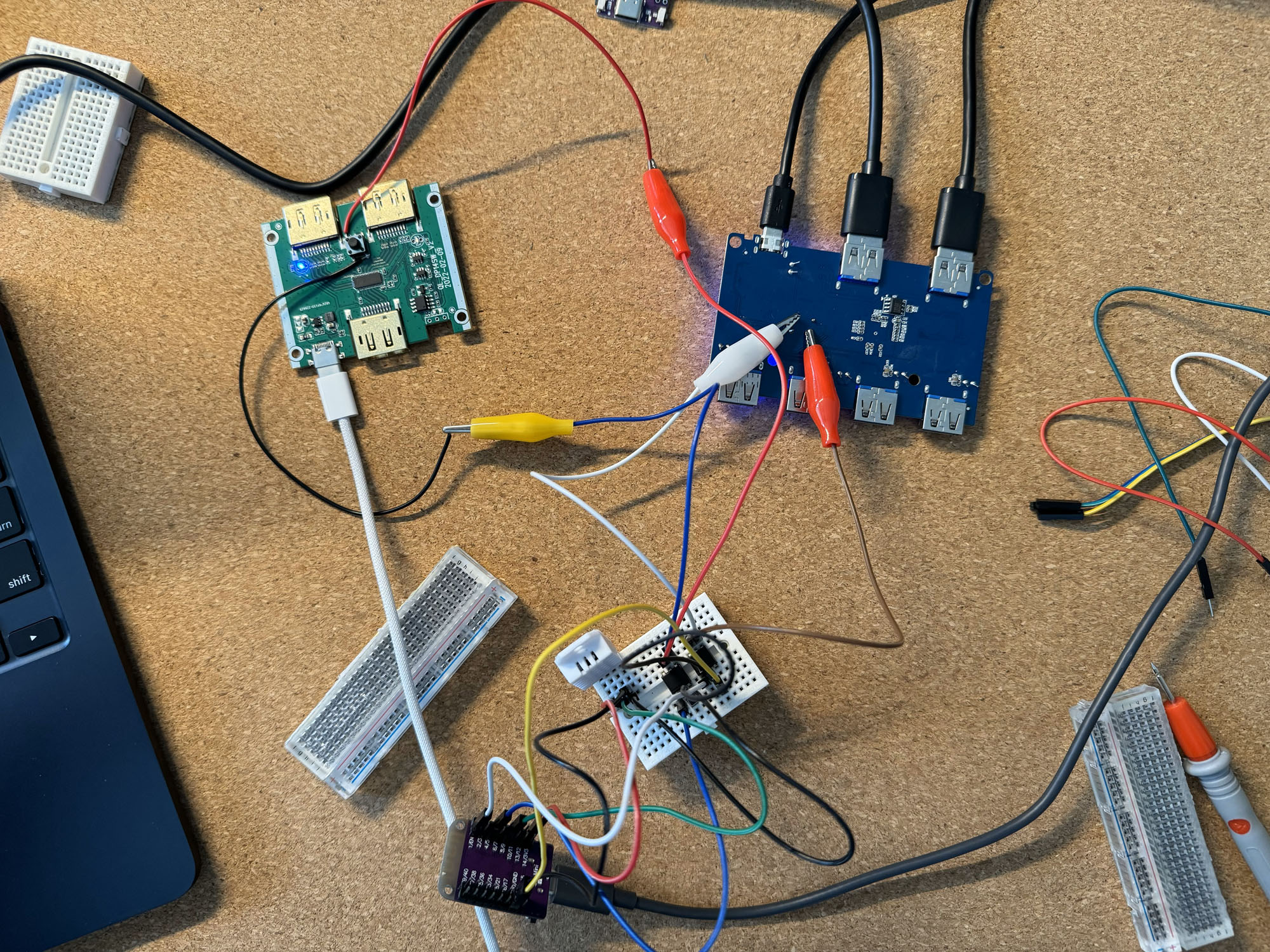
[Current workflow pictured below]
Goals
I wanted to fix the usability of the switches while integrating them into an office control panel. I devised three significant requirements that my desired solution had to meet.
- The first requirement was that both switches be hidden from sight. I had the idea to mount the switches to the underside of our desk towards the back to achieve this. This would allow the cables to reach the switches while keeping them hidden.
- The second requirement was that I should be able to control the switches from our Home Assistant Dashboard. To aid in this requirement, I decided to use an existing framework called ESPHome, which can be flashed onto an ESP module and wired up to control the switches.
- The third requirement was cost; the solution had to be cheap. A simple solution would be to buy a prebuilt switcher (or KVM); however, to reduce e-waste, I wanted to reuse the parts I had while also keeping the cost down to not infringe on the price of a prebuilt.
I also decided to add the stretch goal of integrating a temperature and humidity sensor into the new device; this was a fair addition as I planned to use an ESP32 board to control the switches, and it had extra headroom for further sensors or controls.
Implementation
The first step in the solution was to discover how I would control the switches. Each switch has a built-in button that allows you to control the input or output. Using a multimeter, I found that bridging two pads of this button would trigger the switch action and change the output device. Further testing revealed that the pad with a voltage of 0 just required a voltage pulse that would also trigger the switch; therefore, to control the switches, I could send a pulse of power from the ESP model to each switch and attach the other pad to ground to complete the circuit. This enabled us to control the switches with the ESP32 module.
To control the ESP module, I relied on the existing ESPHome framework. This framework enabled me to program and integrate the module efficiently with my existing home assistant environment. To configure the ESP module, I needed to upload a structured YAML document that describes how the module should behave. Below is part of the YAML document I used to configure the module.
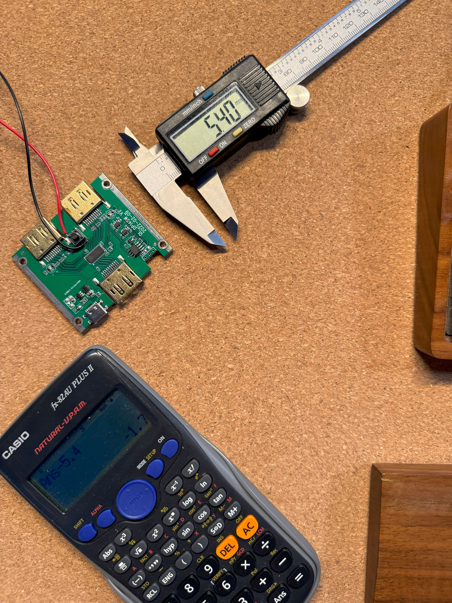
The second step was designing an enclosure for the final product. To do this, I used Fusion360, taking top-down photos of each component alongside a ruler so that I could import the images and size them to scale. I then created simple mocks of each component and placed them in 3D space to create a general layout for the housing of the finished device. Utilising a Prusa 3D printer, I rapidly printed prototypes of the case to see what was and wasn't working. After a few failures and errors, I settled on the final design of the case.
Implementation
My main challenge was the material I used for the prototype cases. Although PLA is suitable for most tasks, it lacks heat resistance. These small electronics can get warm and reach PLA's glass transition temperature (GTT). To ease this concern, PETG was chosen as the material for the final product as it has a higher GTT. This material selection introduced some new hurdles. One particular issue I ran into with PETG was its tendency to cause stringing during printing, leading to a material buildup in unwanted places. To reduce the occurrence of the PETG filament stringing, it was dried for an extended period, the print nozzle temperature was decreased by 5 degrees, and the print supports were switched to organic, which reduced their footprint, resulting in the print head needing to travel in across gaps less often.
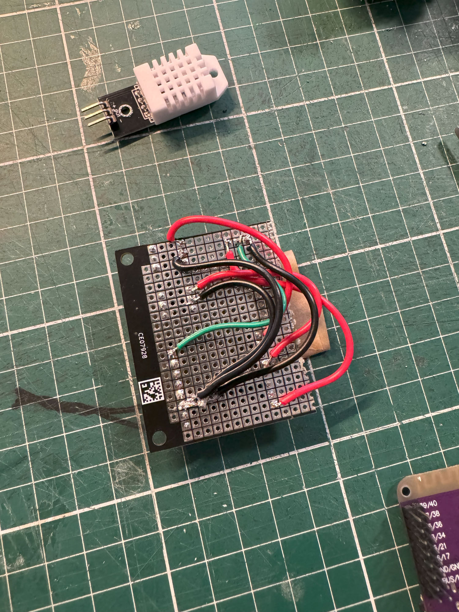
Once the final case print had started, I began wiring and soldering all components together. Although it increased costs, a decision was made to add female connectors to the prototype board. As I was not soldering the parts directly to the prototype board, the more expensive parts could be replaced if they broke or reused if the project was decommissioned.
During testing, the device failed to read temperature sensor data and control both switches. Upon further inspection, I noticed during the soldering phase that the ground wires had yet to be soldered to the correct pin on the ESP32 module. The fix required the annoying and painful process of desoldering the wires and moving them to the correct pin.
Once the case had finished printing, I used a heat gun to remove any stringing that had occurred. I then heat-pressed in the brass threads that would be used to secure all the components and close the case. Then, using a hot glue gun, glued in place some neodymium magnets that would be used to mount the device to the underside of our desk easily.
Wrap Up
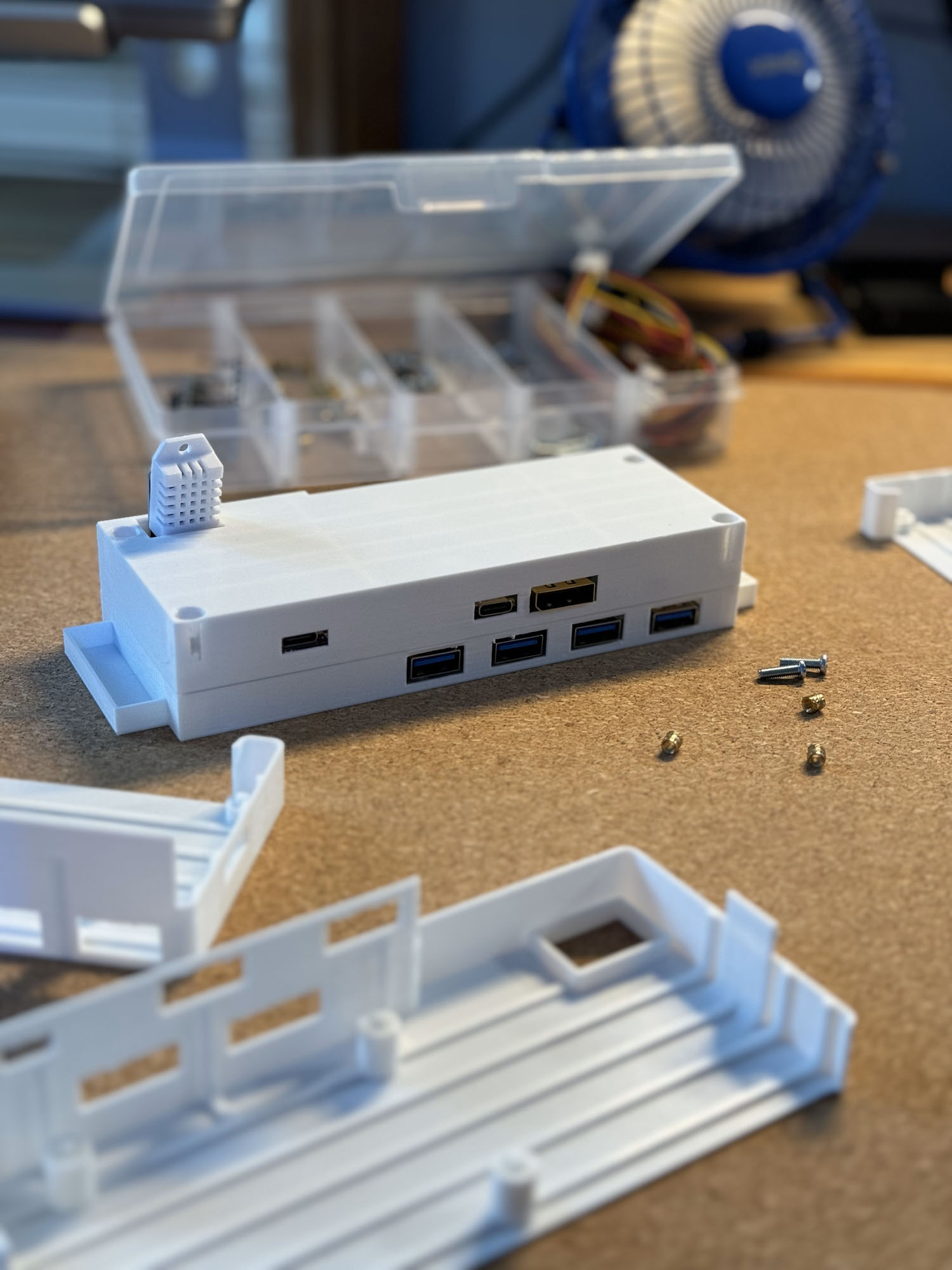
[Smart switcher workflow pictured below]
The smart switcher has been deployed for two weeks now. We can call the project a success with only one or two hiccups while using it. If I were to do the project again, I would like to add a few creature comforts.
- First, correct the case to match the depth of the DisplayPort switcher board. Because the display port switcher board was smaller than the USB switcher boards, the ports on one side didn't quite reach; the solution was to shave away the hole to make it large enough for cables to fit through. Fixing this in the next version would be a great benefit.
- Secondly, having a way to identify which computer is currently in control of the USB switcher would be good information. Neither switcher provides this information; however, it is much easier to tell which computer is currently in control of the display.
The result's ease of use and cleanliness can not be overstated; switching between computers is now seamless.
Key Learnings
- PETG is more susceptible to stringing compared to PLA
- Taking overhead photos by hand can result in slight variations in sizes. It is best to set up a jig that can be used to take accurate photos.
- The ESP32 Mini S2 has different steps to flash the device.


